This article discusses some of the details that affect the choice of operating frequency for switching power supplies – efficiency, noise, etc.
As the name suggests, switching regulator do DC/DC conversion by turning something on and off. In a typical inductor-based circuit, the switch controls the current flowing through the inductor; in a charge-pump-based regulator, the charge from the input supply is “pumped” through the switch onto the capacitor. Switching is a periodic thing, so switch-mode regulation is never far from a frequency problem.
I’m sure you’ve noticed that switching regulator ICs have a wide frequency range. I would say the typical range is 100 kHz to 2 MHz, but you can find frequencies below 100 kHz, and some parts will be significantly higher (up to 3 or 4 MHz). You may also notice that many switch mode ICs allow you to select the operating frequency (within a specified range) via an external resistor. Why do parts offer such a wide range of frequencies? What is the correct frequency for a given application? let’s see.
The effect of switching frequency
Switch mode DC/DC converters are not that simple when you start getting into the details. In fact, they’re not even close to being simple, the switching frequency is a fundamental parameter that affects every aspect of a circuit’s function and performance in some way. So I’ll focus on the most important and practical considerations, and I’ll try to be as accurate as possible without burying myself in the complicated details.
The following subsections are written from the perspective of inductor-based switches, but this does not mean that none of this information applies to charge pump regulators.
noise
When I think about switching frequencies, the first thing that comes to mind is noise, whether conducted or radiated. Switching noise cannot be eliminated by shifting the frequency up or down, but you can reduce the noise problem.
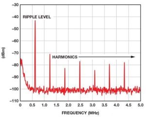
The basic idea here is that your switcher will generate noise at the switching frequency and harmonics of the switching frequency.
By tuning the fundamental, you can “control” the noise so that it doesn’t conflict with sensitive analog circuits or FCC emission limits.
Example: Suppose your converter is very close to an ADC sampling a 50 kHz baseband waveform. If your switcher operates at 1 MHz, you will be able to suppress noise related to the fundamental and all harmonics using a single-pole or (better) double-pole low-pass filter.
Using a higher switching frequency is sometimes an easy way to deal with noise because you can solve the problem more efficiently by adding a low pass filter. However, you need to make sure you don’t push the noise into bands with lower emission limits or into bands.
effectiveness
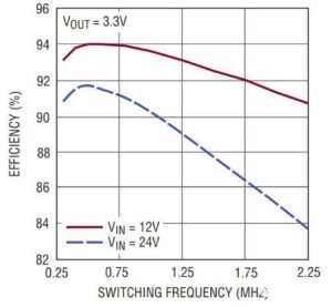
We do not want to reduce the efficiency of a high-efficiency switching regulator simply by choosing an inappropriate switching frequency. The basic idea here is that higher frequency means lower efficiency.
This makes sense if you think about it: switch-mode regulation is effective because it takes advantage of the low power consumption associated with the “fully on” and “fully off” states of the transistors. Significant power dissipation occurs only in the intermediate region between on and off, and if the transistor switches between on and off more frequently, you will waste more power and efficiency drops.
The figure below provides an example of the relationship between switching frequency and efficiency.
board space
The versatility and high efficiency of switching regulator make them an attractive choice for small battery-powered devices. This means that PCB area is sometimes a critical factor in the design process. An important vote in favor of higher switching frequencies is reduced board space: in general, higher switching frequencies allow the converter’s output filter to achieve performance comparable to lower capacitance and inductance values, with lower capacitance and Inductance values correspond to smaller capacitors and inductors.
ripple
The first subsection (titled “Noise”) deals with disturbances created by the switching action of the converter, which are then coupled or radiated into other parts of the system or into nearby electronics. This is different from “ripple”, which refers to the periodic variation that exists directly in the converter’s output voltage.
The importance of ripple varies by application. Digital circuits are very resistant to power supply ripple, but some analog components are also very tolerant. For example, components with good power supply rejection ratio (PSRR) at the relevant frequency.
The basic relationship here is that higher switching frequency means lower ripple. The following image gives an example of this effect:
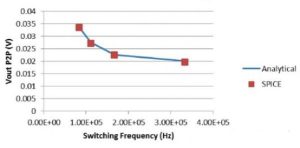
From this graph you can see that higher switching frequency results in lower ripple.
However, you need to be careful. Because if you increase the switching frequency, you may move the ripple frequency up to a frequency band. The frequency band is the place where the analog components have lower PSRR. In practice, this is quite possible, since PSRR tends to decrease with increasing frequency. However, you might get lucky and end up with components like Maxim’s MAX40018:
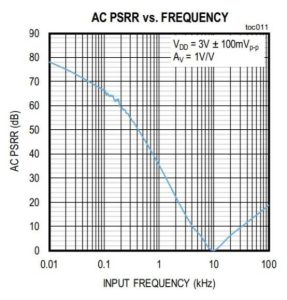
PSRR initially decreased with frequency, as expected, but then increased after 10 kHz. (Although we don’t know what happens after 100 kHz.)
Summary
The switching frequency of a DC/DC converter affects many aspects of circuit function. In my opinion, the most important relationships are as follows:
The higher the switching frequency, the easier the noise is to control (through filtering). But we should adjust the frequency according to the noise characteristics and requirements.
The higher the frequency, the lower the efficiency.
Requires less board space when using higher frequencies (because passive components can be smaller).
An increase in switching frequency results in a decrease in ripple amplitude.