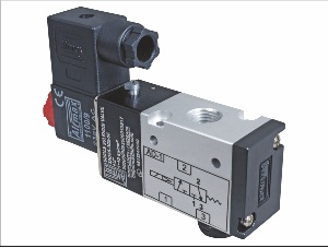
A pneumatic valve is one that works inside a pneumatic system (one that uses pneumatic air or gas).
- What is a pneumatic valve?
- Pneumatic valve types and design
- Pneumatic flow control valve working principle
What is a pneumatic valve?
A pneumatic system uses a difference in pressure of compressed gas or air to operate. Different mechanisms using to distribute pneumatic gas through such schemes. Together, they form a central system.
In this structure, valves use to control, distribute, and direct the flow. Using locking and regulating elements, they serve as dosing and guiding elements. Thus, pneumatic valves function as intermediaries between sources (compressors) and actuators (such as pneumatic actuators or pneumatic cylinders).
Multiple pneumatic cylinders can easily control by the directional control valve. The pneumatic air comes from the air compressor via air pipelines. To operate multiple pneumatic cylinders with one air tank is challenging. Hence the directional control valve comes into action. This directional valve redirects the pneumatic airflow. That airflow operates multiple air cylinders at the same time.
These units control using special signals. Signals utilize to control pneumatic valves include:
Electromagnetic Pneumatic Valves: Magnetic fields control coils and solenoids. The working principle is quite simple. To operate the coils, an electrical current is enable. The valve stem moves when the magnetic field in the coils interacts with the magnetic field in the solenoid valves.
Pneumatic Control Valves: The pneumatic system’s components are control with the help of the same pneumatic air stream. Its presence or absence affects its function under certain conditions.
Mechanical Pneumatic Valves: Mechanically driven, for example, by a lever. There are many options, such as 90-degree steps or quarter-turn versions. These are typically running for simple tasks (opening and closing).
In addition to the main categories, combination control devices are also available in the market. Some valves are running manually, such as by pressing a button.

Pneumatic valve types and design
There are a number of flow lines (ports) and positions that determine the type of valve. This information is always coming in the valve characteristics.
The first figure shows the number of ports in the device and the second one shows the number of available spool positions. An example of a 4/2 pneumatic valve is that it has four ports and two spool positions.
The number between the numbers is not driving and selection by the manufacturer (4/3, 4-3, etc.). Pneumatic valves most commonly have 3/2 and 5/2 schemes.
Lines indicate the number of connecting holes. Holes and their bundles have specific purposes. They retract and extend the medium and exhaust it. Positions show how many options there are for adjusting the valve’s position.
There are two types of valves based on the initial position of the spool relative to the flow:
- A Normally-Closed Valve: This means that its first state is close (airflow blocking). Upon receiving a signal, the valve openings, thus opening the line section.
- A Normally-Open Valve: Opens the flow line (air is free to move) and closes it when the signal is given.
As well, the way devices return to their original position after completing their work may vary. There are two kinds:
- Mono-Stable Valves: After the signal is terminated, they return to their original positions. This accomplishes by a return spring. A single external signal needs to operate.
- Bi-Stable Valves: Do not return to the original position after the external signal has cease. A special return signal needs to return them to their initial position. As a result, a system like this requires two external signals to operate (on/off).
Also Read: Introduction of Pneumatic Actuator
Pneumatic Flow Control Valve Working Principle
The main purpose of the pneumatic distributor is to alter the cross-section in the pneumatic pipeline, which allows the flow to be adjusted and directed.
A locking and regulating element accomplishes this.
There are two types of section changes: discrete (on / off) and smoothly continuous (with adjustable parameters).
Based on this purpose, the equipment is divided into two types:
- Piston Valves: Discrete flow control valves are designed for this purpose. These valves provide quick channel isolation. These are the best fit for simple systems. They move along the flow line. There are usually only two to three outputs in such a design.
- Sliding Spool Valves: Flow control devices that are more complex are designed. This equipment utilizing in cross-sections with a high flow rate and a complicate circuit. Due to their versatility, spool valves can use in systems with 4-5 working lines as well as in simpler circuits. Perpendicular to the flow axis, the spool moves.
Conclusion: The main regulators of compressed air and gas flow in pneumatic systems are pneumatic valves. As a result of their wide range, they can perform both complicated and simple tasks in flow direction control. Each valve has its own unique design.


