Local hydraulic supply Albuquerque is extremely important for your business. For example, if your hydraulic equipment breaks down on Friday night, you can’t wait two business days for the part to arrive. If you work on the construction side of hydraulics, a local supplier is essential to keep your job on track. They can help you get the parts you need quickly, saving you money and allowing you to complete the job as soon as possible. If you don’t have a local supplier, you’ll end up waiting for days for the part to arrive.
Open-channel hydraulics
This book is the first comprehensive guide to open-channel hydraulics in English. It provides a solid grounding in the fundamentals of fluid mechanics and its application to engineering. The book also covers common hydraulic problems and the latest research in this area. It covers everything from boundary layer properties to flow surface profiles to the principles of velocity distribution. This text is an excellent reference for engineering students and practitioners alike. The information presented in Open-Channel Hydraulics is highly relevant to a variety of fields, including civil engineering, water resources management, and hydrology.
The slope component of gravity and the shape of a channel determine the overall flow resistance in an open-channel hydraulic puller system. A smaller hydraulic radius increases flow contact with rough boundaries and decreases drag. The slope component of gravity is the dominant force in open-channel flow. These factors affect average velocity, but do not alter it. Therefore, a lower ratio of roughness increases contact between the flow and the rough boundary. The ratio between roughness and hydraulic radius is inversely proportional to the slope component of gravity.
The basic equations for open-channel hydraulic systems are based on three fundamental assumptions. The first assumption is that the fluid is homogeneous, the second is that the flow is steady, and the third is that the flow is nonturbulent. The last two are important, but the former is the most widely used. The third assumption is that the flow is hydrostatic. This assumption is fundamental to open-channel hydraulics.
Closed-loop circuits
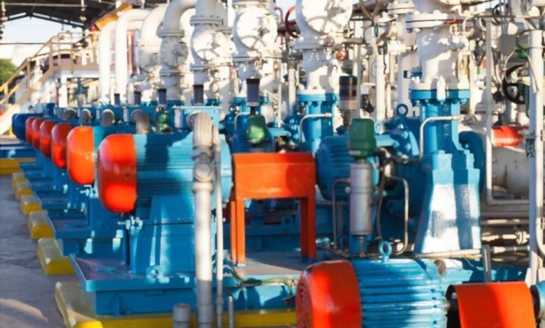
If you’re designing a new hydraulic system, you’ve probably wondered how closed-loop hydraulic supply circuits work. The answer is simple, but you must know that these hydraulic systems are far more complex than they appear. In some cases, the closed-loop design is not necessary for the specific application. Flow to cylinders may be partially or fully open loop. For example, a single rod cylinder doesn’t require a closed loop, because the volume entering one side does not match the volume coming out of the other side, causing a pressure spike and cavitation. But a double-rod cylinder, on the other hand, can operate without a closed-loop design until the end of its stroke.
In closed-loop hydraulic supply circuits, the drive motor provides all the power needed to operate the actuator, while a directional control valve directs the flow to the actuator. Both regulating valves have a spool position that controls the direction of fluid flow, and a variable orifice in the flow regulating valve allows the pump to be controlled from the lowest to the highest point. The closed-loop hydraulic system is highly efficient for pushing and pulling loads, because it doesn’t require valves.
Closed-loop hydraulic control systems work by using a feed pump that receives the same volume of fluid as the main pump. The feed pump is small in comparison to the main pump. Closed-loop hydraulic systems also require a feed pump that has a capacity of up to 15% of the main pump’s capacity. Closed-loop hydraulic systems can be used to control the direction of rotation of the hydraulic motor, and even to provide high-pressure fluid to both ports.
visit now hydraulic supply products: https://www.swseal.com/Hydraulic-System-Components
Non-uniform streams
A non-uniform stream is one characterized by a surface profile with a difference between measured and calculated n values. This variation in the n values can be attributed to uncertainty in determining roughness factors. A non-uniform stream requires different methods of roughness analysis. For example, one cannot use the Manning equation to estimate roughness when the flow is not uniform. Instead, one should use uncertainty analysis methods when estimating roughness.
To calculate the average energy slope of a non-uniform stream, various cross-sectional parameters are measured. Accurate measurement of these parameters is necessary for a correct assessment of the flow. Flow depth is the distance between the bottom of the channel and the water surface. The depth of the stream is the same in a rectangular channel but varies in natural channels. This depth is usually measured relative to the channel thalweg (the curved portion of a channel where water flows from the bed to the water surface). Normal depth is the same for a uniform channel.
Uniform flow can be obtained by installing a hydraulic-jump-stepped spillway. This spillway will have a shallower depth than the non-uniform one. However, this spillway will have stronger aeration. The uniform aerated flow will have a lower energy density than the non-uniform stream. In addition, a stepped spillway will have a greater energy dissipation compared to a single-step spillway.
Control valves
There are several types of hydraulic valves, including pilot actuation, solenoid-operated, and directional. Pilot actuation involves the use of pressurized fluid to move the valve flow control elements. It is useful in flammable environments, where electric or electronic devices may not be appropriate. Electrical/electronic valves may also have a high risk of explosion. To reduce the risk of explosion, consider installing manual valve controls for your hydraulic systems.
In hydraulic systems, these control valves control the flow of fluid through a piping system. They can be used to check the flow level, redirect pressurized fluid, or even close a hydraulic line. Many types of hydraulic valves contain a series of actuators and other mechanisms to regulate their flow. These devices are available in a variety of styles and materials. Among them, you can find the pressure-compensated flow valves, throttling flow control valves, and sequence and counterbalance valves.
Besides the valve’s body material, hydraulic solenoid valves also have a magnetic coil, which is the primary component that regulates the flow of fluid. In addition, hydraulic solenoid valves typically have an O-ring set on their connection plates and socket head cap screws with hexagon sockets. They support reliable fastening and tight sealing and can be used in a variety of applications. You can find hydraulic solenoid valves in a variety of sizes and materials, including brass, stainless steel, and PVC.
Leaks
Not all hydraulic leaks are visible and bad. In fact, a vast majority of hydraulic systems include planned leaks, designed with specific functions in mind. OEMs document acceptable leakage levels under normal operating conditions. But even if you don’t see any obvious leaks, you can still detect them by inspecting the hydraulic system. A quick inspection of the hydraulic system will reveal any potential leaks and provide an effective plan for repair or modification.
Internal planned leaks occur through small orifices, which allow fluid to leak into a lower pressurized zone while preventing it from exiting the hydraulic circuit. This type of leakage is usually caused by wear on components during normal operation. Incorrect component selection, manufacturing tolerances, and improper overhaul of rebuilt components can also contribute to internal leaks. Ultimately, internal leaks cause less performance, less efficiency, and decreased reliability. Regardless of the type of hydraulic leak, addressing the issue quickly will help you avoid any major problems.
The cost of repairing hydraulic system leaks can affect a company’s bottom line. It costs a business an unnecessary amount of money. Not only does it cost money, it can also reduce equipment reliability and decrease profits. This can add up to a staggering number of dollars if left unchecked. Leaks can also lead to personal and financial consequences. The time and energy spent to identify and fix a leak is often not worth the effort.
Reservoirs
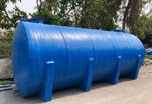
Hydraulic supply systems are usually equipped with reservoirs to provide liquid power. The reservoir provides sufficient space for more than just coolers. A pump-motor group is typically mounted on the reservoir and draws fluid into the suction port. Many power units have filters, level gauges, filler and breather devices. Reservoirs can also be equipped with virtually everything: valve stack/manifold, outside actuators, accumulator, heat exchanger and conditioning accessories.
The capacity of hydraulic supply varies from one to another, and the size must be sufficient to allow thermal expansion of fluids. They should be large enough to accommodate changes in the fluid level during normal system operation. Typically, large reservoirs are used to reduce recirculation. Some types of reservoirs have top-mounted fillers to permit filtered air to enter. Others have side-mounted fillers to keep contaminants out. A reservoir should also include a float/dial gauge that indicates the level of fluid.
A hydraulic reservoir may be pressurized or non-pressurized. Most reservoirs have a rim on the filler neck that is beneath the top portion of the reservoir. They are designed with a means to monitor the fluid level. This means may include a dipstick or a glass tube. In addition, hydraulic reservoirs may be vented or pressurized. Whether the fluid is pressurized or not depends on the intended use.